3D Paths


3D Paths |
  
|
3D path is used as an auxiliary 3D element in many system 3D operations. It represents a spatial curve that may consist of segments of different types.
Any 3D path has direction, and, therefore, the start and end points. The direction of the 3D path will affect the result of using it in various operations.
A 3D path can be open or closed. The start and end points of a closed path coincide.
Methods of creating 3D paths
The command "3PA: Construct 3D Path" is used for creating 3D paths:
Icon |
Ribbon |
|---|---|
|
3D Model → Construct → 3D Path |
Keyboard |
Textual Menu |
<3PA> |
Construction >3D Path |
This command unites various methods of creating 3D paths. Those methods can be divided into two groups:
● Creating 3D paths based on already existing 3D elements:
- 3D path based on a sequence of connected edges;
- 3D path as a 3D spline through 3D points;
- 3D path as a sequence of 3D paths;
- 3D path as a 3D path projection on a face;
- 3D path as a copy of an existing 3D path;
- 3D path as an outline edge;
- 3D path as an offset from a curve (of a 3D Path) lying on a surface;
- 3D path based on a section of a body by a plane;
- 3D path by a parametrically varying 3D node.
● Creating 3D paths based on 2D elements (located on the workplanes or worksurfaces):
- 3D path by a hatch;
- 3D path by 2D paths;
- 3D path by two projections (two 2D paths).
To create an arbitrary 3D path, you need to accomplish the following steps:
1. Select the method of creating a 3D path.
Each method has its separate option within the command's automenu. Upon selecting one or another option, the automenu provides additional options corresponding to the given method of creating a 3D path.
Some methods of creating a 3D path can be automatically activated by the system if you select the source object of a certain type in the 3D scene or in the 3D model tree right after entering the command. For example, selecting a 3D node activates the mode of creating a 3D path by a 3D points; upon selecting a 3D path – the mode of creating a 3D path copy; selecting a 2D path on the active workplane sets the mode of creating a 3D path by 2D paths.
2. Select the source objects for creating a path and the required parameters (if necessary);
3. Confirm the creation by ![]() in the automenu or in the command's properties window.
in the automenu or in the command's properties window.
Creating 3D paths based on 3D elements
Creating 3D path as spline through 3D points
Splines are constructed based on a set of 3D points. The points of the set determined the spline control points. Modifying positions of the source 3D points will affect the shape of the 3D path built through these points.
There are three types of 3D splines:
● 3D polyline is a spatial curve made of straight segments connecting the points of the source set. A polyline can be either open or closed (when a closed polyline is created, the first 3D point of the source set is used twice – for defining the start and the end of the path);

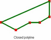
● 3D spline through nodes is a spline passing through all control points. Such spline can be periodic or nonperiodic. When a periodic spline is created, the first 3D point is used twice. When creating a nonperiodic 3D spline through nodes, you can additionally specify the spline direction vectors at the spline's boundaries (the start and the end);


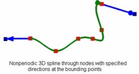
● 3D spline by polyline (a NURBS – non-uniform rational B-spline) – an arbitrary-degree spline by a control polyline. The control points are used for building the control polyline The spline itself does not pass through them (except the first and the last point in the case of an open spline). The spline's parameters allow specifying the degree, weights at control points, parameterization type and positions of the parameterization nodes.
Just like the previous case, the 3D spline by polyline can be periodic or nonperiodic.

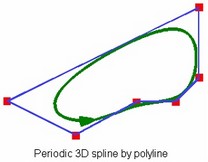
To create a 3D path as a 3D spline, in the command's automenu select the option:
![]() <S> Construct 3D Path as spline based on 3D Nodes
<S> Construct 3D Path as spline based on 3D Nodes
A 3D spline creation usually begins with specifying a set of 3D points through which the spline will be constructed. The following option is used for selecting 3D points:
![]() <M> Add 3D Point to Spline
<M> Add 3D Point to Spline
The selected 3D points are added to the list of the spline control points in the properties window. To exclude one of the points, pick it in the list and click [Delete]. The type of the spline being created – periodic or nonperiodic (closed or open in the case of a polyline) – is also determined by means of the properties window (the check box "Periodic"). When the check is cleared, a nonperiodic spline is created (or an open polyline). When the flag is set, the spline will be periodic (closed in the polyline case). The further steps of the spline creation depend on its type. The spline type selection is also done in the command's properties window (the parameter "Type"). The appearance of the properties window and the automenu changes according to the selected type. |
|
The 3D path as a polyline does not use any more parameters. Its creation is complete at this point.
When creating a 3D path as a spline through nodes, the following pairs of options are available in the automenu for defining spline directions at the bounding points:
![]() <L> Set direction at Spline start
<L> Set direction at Spline start
![]() <R> Set direction at Spline end
<R> Set direction at Spline end
When selecting the option ![]() or
or ![]() , the automenu brings the options for selecting the second point of the direction vector or the vector itself at the corresponding bounding point:
, the automenu brings the options for selecting the second point of the direction vector or the vector itself at the corresponding bounding point:
![]() <N> Set direction at Spline start by 3D Point
<N> Set direction at Spline start by 3D Point
![]() <D> Set direction at Spline start by Vector
<D> Set direction at Spline start by Vector
![]() <N> Set direction at Spline end by 3D Point
<N> Set direction at Spline end by 3D Point
![]() <D> Set direction at Spline end by Vector
<D> Set direction at Spline end by Vector
To define the second point of the direction vector, select an additional 3D point. The direction vector will be pointing from the respective bounding point to the specified 3D point. To specify the direction vector explicitly, you need to select a 3D element suitable for defining a vector in the space. The direction vector is created by the parallel translation of the selected vector to the spline's bounding point.
The length of each directional vector affects the shape of the spline being created - the longer is the vector, the longer portion of the curve is affected by this vector. The vector length can be determined automatically (based on its defining 3D elements) or be manually set by the user. By default, the vector length is taken from its defining 3D elements. For example, when defining the direction vector by a 3D point, the vector length will be equal to the distance between the specified 3D point in the respective bounding point of the spline.
To manually specify the length of the direction vector at the start or at the end of the spline, you need: 1. In the group "Additional parameters" of the command's properties window set the appropriate flag: "Start tangent" or "End tangent". 2. In the input box becoming accessible below, enter the desired vector length. |
|
To abandon the selected direction vector at the start or end of the spline, you can use the automenu options:
![]() <K> Clear direction at Spline start
<K> Clear direction at Spline start
![]() <F> Clear direction at Spline end
<F> Clear direction at Spline end
When creating a 3D spline by polyline, the shape of the curve being created is determined by the spline parameters in the command's properties window: Weight coefficients of all spline's base 3D points. The coefficient must be greater than or equal to 0. The more is the weight of a point, the closer to it the spline will pass. The default value set for all control points of the spline is "1". To modify the value of the weight of the particular point, select it in the list and enter the desired value in the "Weight" parameter's input box. Degree of polynomials of the piecewise-continuous function, describing the spline being created is the "Degree" parameter. The maximum allowed value of the degree is the number of the spline control points minus one. The default degree set for a spline with at least four control points is equal to 3. |
|
The higher is the spline degree, the more "rigid" it becomes. That means, the spline barely reacts to moving a particular control point. The low-degree splines pass closer to the control points, and changes in their positions stronger affect the spline shape.
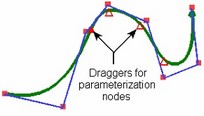
Parametrization type ("By Chord length", "Uniform", "Centripetal" and "Manually"). In the case of the uniform parameterization, the shape of the curve does not adapt to the length of the control polyline segments, which may cause cusps and self-intersections on small segments. The two other types of parameterization ("by Chord length" and "Centripetal") this does not happen, while different lengths of the polyline segments make different contributions. The effect of the parameterization type on the shape of the curve being created is nonlinear and may differ case-by-case.
In the case of the manual parameterization, the user can change the shape of the curve by manually changing positions of the spline parameterization nodes. The most convenient way is to do this directly in the 3D scene by the draggers defining positions of each parameterization node.
3D path by connected edges
A 3D path is created by a set of edges of an operation body, 3D profile or another path. The set is defined by subsequently selecting its member edges. The selected edges must be connected with each other, forming a continuous chain. A set consisting of a single edge is also allowed.
A connected sequence of smoothly joined edges can be found by the system automatically upon selecting one of its member edges.

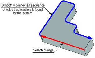
This method of creating a 3D path can be set by the following automenu option provided in the command:
![]() <E> Construct 3D Path using edge sequence
<E> Construct 3D Path using edge sequence
Upon turning on this mode, the following auxiliary option activates automatically in the automenu:
![]() <E> Select Edge
<E> Select Edge
This option allows selecting all necessary edges by subsequently picking them in the 3D scene by ![]() .
.
For automatic selection of editing connected sequence of smoothly joined edges, you need to activate another option:
![]() <S> Smooth edge chain selection mode
<S> Smooth edge chain selection mode
Upon activating this option, simply select any edge that belongs to the intended sequence. The rest of the edges will be selected automatically.
To exclude several consequent selected edges starting from the last one, use the option:
![]() <D> Delete last Edge from 3D Path
<D> Delete last Edge from 3D Path
To cancel selection of all edges at once, use the option:
![]() <К> Cancel selection
<К> Cancel selection
3D path as a sequence of 3D paths
This method allows creating a 3D path by combining an arbitrary number of 3D paths. Any paths are allowed as the source, except closed ones.
The resulting 3D path is created as follows: the start of the second path is carried over to the end of the first selected 3D path by parallel translation, the start of the third one is carried over the end of the second, and so on. Each subsequent path is connected to the end of the previous one.

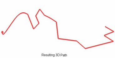
To create a 3D path in this way, select the option:
![]() <T> Construct 3D Path using 3D Path sequence
<T> Construct 3D Path using 3D Path sequence
Selection of 3D paths is done in the 3D scene (by ![]() ) or in the 3D model tree with the activated option:
) or in the 3D model tree with the activated option:
![]() <T> Select 3D Path
<T> Select 3D Path
The last 3D path selection can be canceled by the option:
![]() <D> Delete last 3D Path
<D> Delete last 3D Path
3D path as a 3D path projection on a face or operation body
A 3D path can be created as a projection of another already existing 3D path on all faces of an operation body or on a separate face. In the case of mapping on all faces, select the operation body itself, on an isolated face – a specific face.
Projection on a face is constructed as the intersection line between the selected face and a surface created by extruding the source path in the direction of the projection vector. When mapping on an operation body, then projections of the path are created on each face. The resulting elements (that is, the results of mapping the path on each face) are combined in one path. The elements that cannot be connected are discarded.
When creating a 3D path as a projection, only those pieces of the 3D path are used that fully map on the selected face or body.
When creating a 3D path, the first segment of the source 3D path must be among the resulting mappings.
The vector of mapping (projecting) the source path is defined either with two 3D points, or using some 3D object suitable to define a straight line (this could be, for example, a straight path, an edge, an LCS). If the projection vector is not specified, then:
- When projecting on an isolated face, the normal to that face will be used.
- When projecting on all faces of an operation body, each point of the source path is extruded towards a point on the selected body which is nearest to the former point.
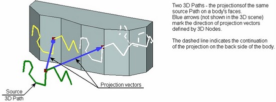
To create a 3D path as a projection of another 3D path, select the option:
![]() <J> Create 3D Path as projection on Face or on Body
<J> Create 3D Path as projection on Face or on Body
The 3D path creation begins with selecting a body or face on which the path will be mapped. To select those, use the following options:
![]() <В> Select operation on which 3D path will be mapped
<В> Select operation on which 3D path will be mapped
![]() <F> Select face that will be used for 3D Path projection
<F> Select face that will be used for 3D Path projection
The face or operation body are selected in the 3D scene by ![]() . An operation body can also be selected in the 3D model tree by picking the intended operation in it.
. An operation body can also be selected in the 3D model tree by picking the intended operation in it.
The source 3D path is selected by the option:
![]() <T> Select 3D Path for projecting onto face
<T> Select 3D Path for projecting onto face
The projection vector can be defined by two 3D points with the help of the options:
![]() <M> Select first 3D point of projection direction vector
<M> Select first 3D point of projection direction vector
![]() <S> Select second 3D point of projection direction vector
<S> Select second 3D point of projection direction vector
The projecting vector can be defined by a single object using the option:
![]() <L> Select projection direction
<L> Select projection direction
To undo a specified direction, use the option:
![]() <K> Cancel selection of projection direction
<K> Cancel selection of projection direction
Creating copy of 3D path
To create a 3D path as a copy of an existing path, simply select the source 3D path. The new path will coincide in the space with the source 3D path. If any transformations are specified among parameters of the created path, those will be performed with respect to the global coordinate system. Additionally, one can specify the source in the target coordinate systems. As a result, copying will be done in the direction from the source to the target coordinate system. The transformations defined for the path in this case will be performed with respect to the specified transformation location.
The resulting path could be a copy of just a portion of the source 3D path. To do this, specify the start and end limits for copying: two 3D points on the source path defining the portion to be copied. If the selected 3D points do not lie on the source path, the boundaries of the portion to be copied are determined by the points on the path that are nearest to the specified points.
You can also specify just one copying boundary. In this case, the opposite end of the path will be used as the second boundary.
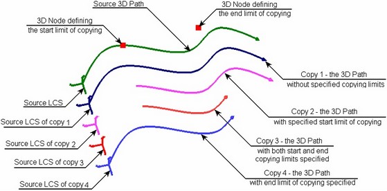
To create a copy of a 3D path, use the following option in the main command's automenu:
![]() <М> Create Copy
<М> Create Copy
Creation of a path copy begins with selecting the source 3D path. A 3D path is selected either directly in the 3D scene or in the 3D model tree. For this, use the automenu option:
![]() <T> Select 3D Path
<T> Select 3D Path
To select the source and the target coordinate systems, the following options are provided:
![]() <1> Select source LCS
<1> Select source LCS
![]() <2> Select target LCS
<2> Select target LCS
If the source or target coordinate system doesn't exist, it can be quickly created using the following options:
![]() <F> Select Point for creating source LCS
<F> Select Point for creating source LCS
![]() <W> Select Point for creating target LCS
<W> Select Point for creating target LCS
As a result, LCS will be automatically created with the vertices at the specified 3D points and the same orientation of the axes as that of the global coordinate system.
To cancel a selection of the source or target coordinate system, you can use the option:
![]() <F> Cansel LCS selection
<F> Cansel LCS selection
The copying limits are defined by the following options:
![]() <S> Set starting copying limit
<S> Set starting copying limit
![]() <E> Set ending copying limit
<E> Set ending copying limit
![]() <D> Clear copying limits
<D> Clear copying limits
3D path as an outline edge
Creating a 3D Path as an outline edge can be found useful for defining the separation line when designing diecast molds.
Construction of a body's outline edge can be schematically described as follows: imagine that spatial lines are drawn parallel to the viewing direction through each point on the body's surface. The points on the body surface in which such a line just touches the body (without intersecting it) are the candidate points for an outline edge.
To create a 3D path, the source body and the viewing direction are specified. The system analyzes the surface of the body, searching for points satisfying the outline edge definition. The resulting set of points is united in one curve – the 3D path.
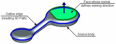
If it is impossible to join all found points into one curve, the system returns a set of separate outline edge segments. The user is offered to select the segment that will be used for building the resulting 3D path. One can select multiple outline edge segments simultaneously. In this case, multiple 3D path will be created rather than a single one, according to the number of selected segments.

A situation as possible when the vector of the viewing direction is parallel to some of the body's faces. In this case, all points of such face satisfy the definition of the outline edge, that is, the system finds an outline "surface" instead of an edge. This situation is resolved by the system by constructing the outline edge through the first points encountered on such face. As a result, most often, the outline edge is constructed along one of the side edges of such a face. A better shape of the outline edge will be obtained by applying the "vertical" face processing. In this mode, the system draws the outline edge straight across the face.

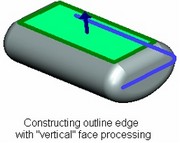
The mode of processing “Vertical” faces is turned on in the command’s properties window.
The mode of processing “Vertical” faces is turned on in the command’s properties window.
To create an outline edge, in the command's main automenu select the following option:
![]() <O> Construct 3D path as an outline
<O> Construct 3D path as an outline
The body whose outline edge will be constructed is selected by the option:
![]() <1> Select Solid Body
<1> Select Solid Body
The viewing direction is defined either by two 3D points or by one 3D element suitable for defining a vector:
![]() <2> Select First point of Direction
<2> Select First point of Direction
![]() <3> Select Second point of Direction
<3> Select Second point of Direction
![]() <4> Select direction
<4> Select direction
After specifying the source body and the viewing direction, the image of the created outline edge will be shown in the 3D scene.
In the case when the system cannot create a single outline edge, the 3D scene will show one of the identified outline edge segments. To create a 3D path based on it, simply confirm the path creation by ![]() .
.
The full list of found outline edge segments is displayed in the command’s properties window. To create a 3D path based on another outline edge segment, it is possible to select the desired segment in the properties window or use the additional option:
![]() <Tab> Change Outline
<Tab> Change Outline
This option allows us to loop through the outline edge segments found by the system (when pressing this option the next segment of the outline edge is displayed on the screen). The segment selected in the list is displayed with a light blue color in 3D scene.
To create a 3D path by several segments of the outline edge, it is necessary to find all desired segments in the list and checkmark them, and then confirm the path creation with the help of ![]() .
.
Creating offset to 3D path
This way of creating a 3D path allows creating 3D curves of the following types:
1. 3D path as an offset from a flat 3D path
2. 3D path as an offset from a 3D curve on a surface
3. 3D path as a 3D offset from a 3D path.
All the methods of creating the 3D path as an offset from another 3D path are united in the automenu under the option:
![]() Construct 3D Path as offset to existing 3D Path
Construct 3D Path as offset to existing 3D Path
The drop-down list of this option contains three choices of creating a 3D path as an offset.

ЗD path as offset to a planar 3D path
To create a path - an offset to a planar 3D path, select the source path and specify the shift with respect to the source 3D path. The shift can be defined in two ways:
By specifying a 3D node through which the offset should pass. The node must lie in the plane of the source path. By a numerical value of the shift of the offset path from the source path. The figure presents an example of creating an offset path with the shift defined by a 3D node.
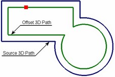
Creating this kind of a path is similar to creating a 3D profile as an offset to another planar 3D profile (see the chapter "3D profiles").
The gaps introduced between the segments of the offset path can be processed in three ways:
Continue – the curves making up the source path are continued. Straight lines are continued straight, arcs are rounded up.
Fillet – a fillet is created between the end points of the neighboring segments of the path being created.
Extend – straight lines are added to the hanging points that are tangent to the path segments at the gaps.


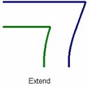
When creating an offset to a path of the complex shape, self intersection loops may occur in the contour of the new path. An additional loop trimming mode helps removing those automatically.

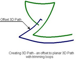
To create a 3D path as an offset to an existing planar 3D path, use the option:
![]() <F> Construct 3D Path as offset to planar 3D Path
<F> Construct 3D Path as offset to planar 3D Path
The first step in creating the 3D path is selecting the source planar 3D path by the option:
![]() <T> Select planar 3D Path
<T> Select planar 3D Path
After that, one has to specify the required shift by a 3D node or numerical value. The 3D node is selected by the option:
![]() <N> Select 3D Vertex in the plane of selected path
<N> Select 3D Vertex in the plane of selected path
To reject a selected node, you can use the option:
![]() <K> Cancel 3D node selection
<K> Cancel 3D node selection
The numerical value of the shift is specified in the command's properties window. Here, other offset parameters are defined as well. The option of processing gaps introduced by creating the offset path is defined by the parameter "Gap Type". The mode of deleting loops turns on upon setting the flag "Remove loops".

3D path as offset to 3D curve lying on surface
To create a 3D path as an offset to a 3D curve on a surface, select the source curve – a 3D path. The offset will be constructed by shifting the points of the original curve by the specified distance along the surface of the face on which the source curve lies. The source 3D path must necessarily lie on a face of a body – either solid or sheet.

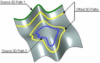
The face on which the selected 3D path lies is defined by the system automatically. Whenever possible, the user is offered to change the system selection (for example, if the 3D path was created on an edge dividing two faces of a body).
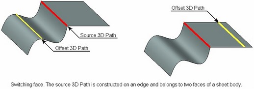
Shifting the offset from the source curve can be defined by a numerical value or by a tabulated function. The table definition of the shift distance allows creating an offset with variable shift from the source curve. The shift table determines the position of control points on the source path and their respective shift values.
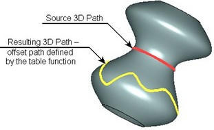
The accuracy of constructing the resulting 3D path is defined either by the number of points, through which the path is created, or by the offset tolerance. When using offset tolerance, the path is constructed in such a way that the resulting curve-to-chord distance for any given pair of sequential points does not exceed the specified accuracy value. The more use the number of points set for the offset or the higher use the specified accuracy, the more precisely the offset path will be constructed.
To create a 3D path as an offset to 3D curve on a surface, use the option:
![]() <D> Construct 3D Path as offset to 3D curve on a surface
<D> Construct 3D Path as offset to 3D curve on a surface
Upon activating this mode, select the source 3D path by the option:
![]() <Z> Select path on surface
<Z> Select path on surface
The offset of an equidistant and its construction accuracy are defined in the properties window or in the path parameters dialog (the option ![]() ). To define an offset by a numerical value, set “Offset Type” to “Constant” and enter the desired value in the “Offset” field. To use a tabulated offset function, set the “Offset Type” parameter to the value “Function”. The [Offset Table] button appears in the dialog that brings up the window to define the table of offsets.
). To define an offset by a numerical value, set “Offset Type” to “Constant” and enter the desired value in the “Offset” field. To use a tabulated offset function, set the “Offset Type” parameter to the value “Function”. The [Offset Table] button appears in the dialog that brings up the window to define the table of offsets.


The "Offsets" dialog allows creating or editing the table of shifts. To add a new row, set the cursor on one of the existing rows in the table and click [Add]. The "Offset" dialog will appear on the screen. In it, specify the position of the new control point (the parameter "Length") and the amount of its offset (the parameter "Offset").
The "Offset" dialog is also used for editing an existing row in the table (by clicking the button [Edit]).
The button [Delete] allows deleting the selected row from the table of shifts.
The table of offsets can be also defined using a plot (graph). To do this, use the button [Graph]. Upon clicking this button, the window to edit a plot appears. Details about working with plots are described in the chapter “Graphs”.
To define the accuracy of constructing the resulting path, decide on the parameter to use for this purpose – "Number of Points" or "Tolerance" – and enter the value of the chosen parameter in the field at the right. The face on which the offset is being created can be replaced by the option:
![]() <Tab> Select other adjacent Face
<Tab> Select other adjacent Face


The "Offset Direction" switch in the offset properties dialog can be used for the same purpose.
3D path as 3D offset to a 3D path
To create a 3D path as a 3D offset, all you need is just to select the source 3D path (of any shape), the offset distance and offsetting direction. The offsetting direction will define the direction of offsetting each point of the source path. A 3D spline will then be constructed, uniting all such points created by offsetting.
A 3D path created as a 3D offset can be used, for example, in CAM processing for creating tool movement trajectories accounting for the tool radius correction; also, in diecast mold design for creating the separation surface (using the outline edge and an offset to it).
There are two ways of defining the offset direction:
● Direction vector. A single direction vector is defined for the whole offset – by two 3D points, a straight edge, a normal to a flat face or workplane.
To yield the offset, each point of the source 3D path is shifted by the specified distance along the vector defined as the cross product of the tangent to the path at the given point and the specified offset direction vector. That means, a point being offset is shifted in the direction perpendicular to both the direction vector and the tangent to the source path.

● Direction from body. This way of creating a 3D offset implies creation of a 3D Path as a "continuation" of a sheet body surface (tangentially). The offsetting direction is defined by the operation body, whose surface needs to be extended. The source 3D path must lie on the same body.
We recommend using a sheet body that lies in one surface, while the source path – a 3D path constructed along the bounding edges of this sheet body. Use of other configurations of the source data leads to an undetermined result of the offset creation.
To make the offset, each point of the source 3D path is shifted by the specified distance along the vector defined as the cross product of the path tangent and the normal to the guiding surface at this point.
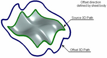
An additional provision of offset with rotation can be used together with any method of creating an offset. In this mode, the offset vector calculated for each point of the source path is additionally rotated about the path tangent at that point by the specified angle. The 3D offset with rotation can be useful, for example, in CAM operations – for constructing a guide path defining the tool inclination angle.

To create a 3D path as a 3D offset, use the option:
![]() <D> Construct 3D Path as offset to 3D Path
<D> Construct 3D Path as offset to 3D Path
The first step in creating the 3D path is selection of the source 3D path by the option:
![]() <A> Select 3D Path
<A> Select 3D Path
After that, you need to define the offsetting direction.
To define the direction by the direction vector, the following options are used:
![]() <B> Select first Point of Direction
<B> Select first Point of Direction
![]() <C> Select second Point of Direction
<C> Select second Point of Direction
![]() <D> Select straight Direction
<D> Select straight Direction
The first two options (![]() and
and ![]() ) allow defining the direction vector by two 3D points. The option
) allow defining the direction vector by two 3D points. The option ![]() serves to select a 3D object suitable for defining the direction vector at once.
serves to select a 3D object suitable for defining the direction vector at once.
To define the offset direction from a body, use the option:
![]() <G> Select Solid Body
<G> Select Solid Body
The offset amount is specified in the command properties window or in the path parameters dialog (the option ![]() ).
).
The shift of the offset is specified in the "Distance" parameter. Here, the offset with rotation mode can also be turned on (if necessary). For this, simply enter the desired value of the rotation angle in the field of the "Angle" parameter (the default value is set to "0").

Creating 3D Path based on body section by plane
To create the 3D path, you need to specify the dissecting workplane and the source body (operation). The path will be created along the intersection contour between the body and the workplane.
The 3D path is constructed only if a single contour results from dissecting the selected body by the plane. If the source body is solid, the contour will be closed. Dissecting a sheet body results in an open contour.
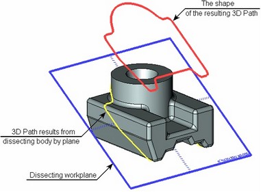
This mode is initiated by the option:
![]() <В> Create 3D Path as intersection of Body and Workplane
<В> Create 3D Path as intersection of Body and Workplane
The command's automenu provides the options for selecting the dissecting plane and the operation body:
![]() <1> Select Secting Plane
<1> Select Secting Plane
![]() <2> Select Operation
<2> Select Operation
Creating 3D path by parametric variation of 3D point
The way of creating a 3D path by parametric variation of a 3D point is used for creating trajectories of complex geometry.
A spatial curve of the path results from "sweeping" a 3D point along an arbitrary or specifically defined spatial trajectory. "Sweeping" of the point is realized by multiple copying of the source 3D point. The resulting set of points is joined by a spline, and a 3D path is built. The resulting 3D path can be closed.
When constructing such path, a general mechanism is used that provides the final result based on parametrical copying of the source element. This mechanism is used in the "By Parameters" operation – when creating a body based on "sweeping" (copying) a profile. It is also used in the "Parametric Array" operation, where the result of the operation is a set of parametrically varying copies of the source object.
This algorithm is described in most details in the chapter "By Parameters". The current chapter provides only a brief description and some examples of using this mechanism.
To create a 3D path by a parametrically varying point, you need to define the law, according to which the copies of the source 3D point will be constructed.
A so-called current copy's coordinate system is calculated for each copy of the point. Copying the 3D point is done in the direction from the source coordinate system to the calculated target coordinate system of the current copy. The user can select one of the local coordinate systems available in the model as the source coordinates. If no local coordinate system is selected, then the source coordinate system will be either the global coordinate system or the coordinate system of the first copy, depending on the method of calculating the current copy's coordinate system.
The current copy's coordinate system (that is, its origin and axes orientation) can be defined by one of two methods:
●Free copy orientation. The laws of modifying the coordinate system parameters of the current copy of the 3D point are described by expressions.
●Copy orientation by 3D curves or surfaces. To define the spatial position of the current copy's coordinate system, existing 3D curves or surfaces of other bodies are used. By directing the copy's coordinate system, the user controls the position of each copy of the 3D point.
Directing the copy's coordinate system is done via the operation parameters. There are parameters of two types - driven parameters and driving parameters.
Driven parameters are the parameters whose values are calculated automatically in the process of creating a copy of the point. You can assign independent variables to read the values of such a parameter.
Driving parameters are the entries with the dependencies defined by the user. The entries of the driving variables allow entering arbitrary expressions that can include any system variable. For example, by including a variable representing the ID number of the 3D point's copy in such an expression will make the value of this parameter dependent on the copy number.
Some operation parameters can be sometimes driving, and sometimes driven. The leading parameter "Copy number" is always driven. It necessarily requires an independent variable that would be assigned the current value of the copy number while calculating the operation. The copy number automatically changes during the calculation from 1 up to the specified amount with the increment of 1.
Calculation is done in the following order: first, the copy number is incremented, then the driving parameters are calculated, after which the rest of driven parameters are calculated (if any), and, finally, copying is done. All copies of the 3D point obtained in this way are united in one spline.
The icon for activating this mode is provided in the main automenu of the 3D path creation command:
![]() <P> Create 3D Path by parametric change of 3D Node position
<P> Create 3D Path by parametric change of 3D Node position
Once the mode is active, the following actions become available:
![]() <R> Select 3D Node
<R> Select 3D Node
![]() <1> Select Curve defining position of coordinate system
<1> Select Curve defining position of coordinate system
![]() <2> Select 3D Curve defining X direction of coordinate system
<2> Select 3D Curve defining X direction of coordinate system
![]() <3> Select 3D Curve defining Y direction of coordinate system
<3> Select 3D Curve defining Y direction of coordinate system
![]() <4> Select Surface defining X direction of coordinate system
<4> Select Surface defining X direction of coordinate system
![]() <5> Select Surface defining Y direction of coordinate system
<5> Select Surface defining Y direction of coordinate system
![]() <6> Select source LCS
<6> Select source LCS
![]() <7> Cancel selection of elements defining coordinate system
<7> Cancel selection of elements defining coordinate system
As was mentioned earlier, one can distinguish two ways of creating a path by parametric variation of a 3D point. Let's review examples of each of them.
Free copy orientation method
When creating a path by this method, all that is required is selecting a 3D node, specifying the number of copies and assigning an independent variable to the "Copy number" parameter. By using the variable assuming the value of the current copy number, one can create certain dependencies in the driving the variable entries, as well as in 2D or 3D constructions, that, in turn, define the position of the source 3D point.
Example 1
Let's review the use of a parametric path on the example of creating a model of a cam. This example can be found in the library "Examples", the folder "3D Modeling/Paths/Cam.grb". The source data is represented by a graph defining the cam surface.
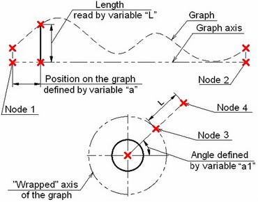
A parametric segment is constructed between the nodes 1 and 2. Its position is defined by the value of the variable "a" in the range from 0 to 1, inclusive. As the variable "a" changes, the line will move from point 1 to point 2. The resulting line will cost the axis of the graph and the graph curve. A segment can be constructed between these points. Its length will be equal to the current value of the function represented by the graph. The read value of the segment length is stored in the variable "L" (by means of the function get).
To construct a 3D Path repeating the contour of the cam surface, one needs to create such a 3D node that will change its spatial position according to the law defined by the graph as the variable changes that is assigned to be the copy counter. Such a node can be conveniently created by adding a few additional 2D constructions based on already available data.
To get the cam of the desired size, the axis of the graph needs to be "wrapped" onto a circle of the specified radius. In the given example, the constructed circle has the radius of 50 mm. A new line needs to be created through the circle center at an angle to the horizontal. The variable "a1" shall be assigned to the parameter defining the slant angle of this line.
The node 3 is constructed at the intersection of the circle and the slanted line. The node 4 is constructed at the distance "L" from the node 3 along the slanted line. A 3D node is constructed based on the 2D node 4. For that purpose, a "Front view" workplane was created on an existing page.
Now, we need to relate all variables in such a way that the 3D node would rebuild according to the copy counter changes. This can be achieved by introducing the following expressions instead of fixed values of some variables, that will maintain the dependency from the copy number:
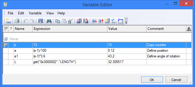
Since the values of the "Copy number" parameter always start from one, sometimes a (–1) adjustment is necessary in the expressions employing the "Copy number" variable.
At this point, the parametric 3D path can be constructed. We need to define two parameters in the parameters dialog: enter the number of copies and assign the variable to act as the copy counter. In the given example, the "Copy number" parameter is assigned the variable "s".


The first copy of the 3D node will coincide in its position with the 101-th. As a result, a closed 3D path will be created. Its geometry will correspond to the cam shape. Next, to create the cam body, extrude the path in the normal direction by 50 units and create a solid body based on the obtained sheet surface using "Sew" operation. Finally, one can make a cylindrical hole along the cam's axis (by extruding a circle with automatic subtraction from the main body).


Method of orienting copy by paths or surfaces
The method of orienting a copy by paths or surfaces is convenient when other means fail that would define the law of varying copy parameters by expressions. In such cases, it could be convenient to use various 3D curves or surfaces for defining the position and orientation of the current copy's coordinate system.
Example 2
As an example of using a parametric 3D path with orientation of the copy by paths or surfaces, let's consider building a 3D path defining the outer border of a "waves" surface. On the figure, it is denoted as 3D path 2. To construct such a path, we need: - the source 3D node whose position will be changing depending on the number of the copy being created in the process of building the path; - a 3D path defining the position of the coordinate system origin for each copy; - a surface, defining the orientation of the X-axis of each copy's coordinate system. |
|
The path being created shall repeat the shape of the outer border of the source sheet body. Therefore, to define the origins of the copies' coordinate systems, we would need to use a 3D path built on the edges of the source sheet body – the 3D path 1.
An auxiliary workplane is constructed in order to get the source 3D node, which is perpendicular to the 3D path 1 and is passing through one of the vertices of the source sheet body. The necessary 2D constructions are created on the workplane. The sought 3D node is created based on a 2D node on the workplane – the Node 2. Node 2 was constructed as follows: first, the Node 1 was created on the workplane with the coordinates (0,0) (corresponding to the vertex of the source sheet body through which the workplane passes). A horizontal line is drawn through this node. A vertical line is drawn at the distance "y" from Node 1, perpendicular to the horizontal line. Node 2 lies on this line at the distance "L" from the lines intersection point. The value of the "L" variable is defined in such a way as to vary with the changes in the copy counter of the 3D path. Therefore, as the 3D path creation progresses, the position of the 2D Node 2 changes by the sinusoidal law with the current copy number, and so does the based on it 3D node.


To define orientation of the X-axis of the copies' coordinate systems with the progress of the parametric path creation, we need to specify the source sheet body itself. If no surface is selected, then the axis orientation will be defined based on the curvature vector of the 3D path 1, whose direction may change abruptly. The following needs to be defined in the path parameters dialog: the number of copies (the variable "q"), the copy counter variable (in the given example, this is the variable "n") and the driving parameter "Parameter along path". Once 3D path 2 is created, the based on it "waves" surface can be created by "Loft" operation. This example is located in the library "Examples", the folder "3D Modeling/Path/ Parametric path with copies orientation by path and surface.grb".


3D paths based on 2D elements
Hatches, 2D paths and 2D splines can be used for a path creation, that are located on the pages associated with the workplanes or worksurfaces. When using a 2D element lying on a page of a workplane, the resulting 3D path will be flat. A 3D path based on a 2D element from a worksurface will repeat the shape of the used surface.
Creating 3D path based on hatch contour
To create a 3D path, select a 2D hatch on a workplane or surface, whose contour is intended for the path. By default, the plane (surface), in which the created 3D path will lie, coincides with the workplane or surface, whose page hosts the source 2D hatch.
For more precise positioning of the 3D path in the space one can specify a 3D node through which the path plane or surface must pass. The plane (surface) of the path is shifted by parallel translation. If that's not enough, the position of the 3D path can be further adjusted by specifying a 2D node (on the workplane hosting the hatch) that shall be aligned with the selected 3D node.
This method of creating a 3D path fully corresponds with creating a 3D profile based on a hatch contour. The detailed description of this capability is available in the chapter "3D profiles".
To create a 3D path by this method, select the following option in the command's main automenu:
![]() <H> Create 3D Path from Hatch
<H> Create 3D Path from Hatch
After activating it, the following options appear in the automenu:
![]() <H> Select Hatch
<H> Select Hatch
![]() <M> Select 3D Node for 3D Path plane fixing
<M> Select 3D Node for 3D Path plane fixing
![]() <N> Select Node to be moved to 3D Node
<N> Select Node to be moved to 3D Node
![]() <K> Break link with 3D Node
<K> Break link with 3D Node
![]() <F> Break link with 2D Node
<F> Break link with 2D Node
Some items may be unavailable at different creation stages. The last icons become available only after specifying the 3D path and its snapping points.
The first step of creating 3D path (and often the only one) is selecting the source hatch. The hatch is selected in the 2D window or on the active workplane, while the ![]() option is active.
option is active.
The workplane or surface with which we edge can tour will be associated is determined automatically by the system. If other workplanes or surfaces also reference the same drawing page, system selection can be altered by the option:
![]() <W> Select other workplane
<W> Select other workplane
This option allows to loop cyclically through workplanes or surfaces up until the desired one is selected.
The 3D node defining the position of the path in the space can be selected by activating the option ![]() . The 2D node on the page of the source hatch is selected with the help of the option
. The 2D node on the page of the source hatch is selected with the help of the option ![]() . The selected nodes can be rejected by the options
. The selected nodes can be rejected by the options ![]() and
and ![]() .
.
Creating 3D path from 2D paths
To create a 3D path, several 2D paths are selected subsequently. The paths must lie on a 2D page (pages) associated with workplanes or surfaces and be open.
The system automatically determines the workplane or surface for each selected 2D path. If the automatic selection is incorrect, the user can fix it manually. A subsequent 3D segment of the path being created is constructed based on the 2D path and the workplane (surface). All resulting segments are joined as follows: the beginning of the second segment is connected to the end of the first one, the beginning of the third – to the end of the second, and so on. In other words, this method can be considered a variation of one of the above-described methods – creation of a 3D path as a sequence of 3D paths.
For more precise placement of the 3D path in the space, one can specify a 3D node to which the plane (surface) of the first 3D path segment will be snapped (that of the one corresponding to the first specified 2D path). Additionally, to adjust the 3D path position, you can specify a 2D node on the page of the first 2D path. This 2D node will be aligned with the selected 3D node.
Creating a 3D path by this method is done with the help of the option:
![]() <C> Create 3D path from 2D Paths
<C> Create 3D path from 2D Paths
Upon activating this mode, a number of auxiliary options appear in the command's automenu for selecting all required objects.
To select 2D paths, use the option:
![]() <C> Select 2D Path
<C> Select 2D Path
![]() <D> Cancel selection of 2D path
<D> Cancel selection of 2D path
The option ![]() allows rejecting the last selected 2D path.
allows rejecting the last selected 2D path.
The system automatically finds the workplane or surface for each selected 2D path. A different workplane or worksurface can be selected (if any exist on the given 2D page) using the option:
![]() <W> Select Other Workplane
<W> Select Other Workplane
The nodes for exact spatial positioning of the 3D path being created are selected by the following options:
![]() <M> Select 3D Node for 3D Path plane fixing
<M> Select 3D Node for 3D Path plane fixing
![]() <N> Select Node to be moved to 3D Node
<N> Select Node to be moved to 3D Node
![]() <K> Break link with 3D Node
<K> Break link with 3D Node
![]() <F> Break link with 2D node
<F> Break link with 2D node
Create 3D Path using two projections
The 3D path is created by two projections on the main workplanes. The projections of the 3D path are represented by 2D paths.
The 2D paths being selected must fully and uniquely define the position and direction of the 3D path in the space. Otherwise, the placement of the 3D path in the space will be incorrect or the system will output a message about an error and a failure creating a 3D path.
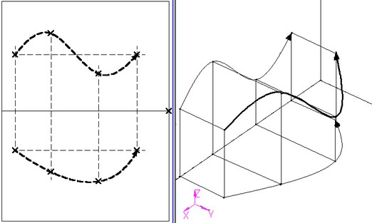
This example is located in the library "Examples", the folder "3D Modeling/Paths/ 3D Path by two 2D Paths.GRB".
This method of creating a 3D path is activated by the option:
![]() <Q> Create 3D Path using two projections
<Q> Create 3D Path using two projections
Upon calling this option, the following options appear in the automenu:
![]() <F> Select first projection (2D Path)
<F> Select first projection (2D Path)
![]() <S> Select second projection (2D Path)
<S> Select second projection (2D Path)
These options allow selecting two projections of the path being created in the 2D view window. The workplanes on which the projections will be placed are selected by the system automatically. A different workplane can be selected (if any exists on the given 2D page) using the option:
![]() <W> Select Other Workplane
<W> Select Other Workplane